








Flanged miniature ball bearings are precision components featuring a solid extended lip on the outer ring. This flange acts as a built-in stop, providing exact axial positioning, simplifying housing design by eliminating the need for internal shoulders, and preventing axial displacement in compact assemblies.
Are you struggling with complex housing designs, tedious machining, or axial displacement in your micro-motors and sensitive instruments?
When space is at an absolute premium, relying on traditional retaining rings or thrust washers often leads to alignment errors and increased manufacturing costs. Upgrading to flanged designs offers a streamlined, drop-in solution that locks your rotating assembly firmly in place.
In this comprehensive guide, we will break down:
- The mechanical advantages of flanged outer rings for axial positioning.
- How to interpret metric and imperial size charts for accurate selection.
- Technical comparisons of shielding and sealing in high-RPM environments.
- Advanced load capacity calculations for miniature scales.
The Anatomy of Flanged Miniature Ball Bearings: Structural Features & Axial Positioning
What Makes the “Flange” Essential?
In the realm of micro-mechanics, every millimeter of space dictates the success of your design. A flanged miniature ball bearing is fundamentally a standard deep groove ball bearing with one critical modification: a solid, extended lip manufactured directly onto the outer ring.
This flange typically extends just a few millimeters beyond the outer diameter (OD). However, its structural impact is massive. It transforms the bearing from a simple friction-reducing component into a definitive locating point for the entire rotating assembly.
By seating the flange against the face of your housing, you achieve immediate, perfectly squared alignment. For a deeper look at our core capabilities, you can explore our complete range of precision miniature bearing solutions tailored for tight-tolerance applications.
Eliminating Thrust Washers and Shoulders: The Physical Advantages in Assembly
Traditional bearing installation requires machining a precise internal shoulder (a step) inside the housing bore to stop the bearing from sliding axially. In miniature applications—such as medical drills or drone motors—machining a microscopic internal shoulder is both expensive and highly susceptible to tolerance stacking errors.
The flanged design completely eliminates this requirement. You only need to bore a straight, through-hole in the housing. The flange rests flush against the exterior surface, acting as a built-in retaining system.
- Reduced Machining Costs: Straight-boring a housing is significantly faster and cheaper than stepped-boring.
- Fewer Components: Eliminates the need for external thrust washers, circlips, or retaining rings, saving inventory space.
- Enhanced Alignment: The flush seating of the flange prevents the bearing from becoming skewed or canted during press-fitting.
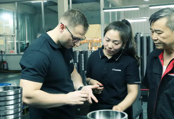
Expert Insight from Jessica Jia (TFL Bearing): “From my experience on the production line, over 40% of premature failures in micro-motors aren’t due to poor bearing quality, but because of misalignment during assembly. “
Vibration Control in High-RPM Micro-Motors
High-speed applications generate significant multi-directional vibrations. When a standard bearing is press-fit into a soft material (like aluminum or plastic housings commonly used in aerospace and electronics), these vibrations can cause the bearing to gradually “walk” or migrate axially out of its seat over time.
The flange provides a hard mechanical stop. When securely fastened or clamped against the housing face, it absorbs thrust loads and dampens resonant frequencies, ensuring the shaft remains perfectly stable even beyond 30,000 RPM. According to foundational studies on bearing vibration dynamics, securing the outer ring mechanically is critical for minimizing high-frequency noise and extending fatigue life in continuous-duty applications.

Decoding the Flanged Bearings Size Chart: Dimensions & Selection Parameters
Metric vs. Imperial: Navigating Bore (d), Outer Diameter (D), and Flange Width (C)
Selecting the correct flanged miniature ball bearing requires a precise understanding of its dimensional footprint. Unlike standard bearings, flanged variants introduce two additional critical measurements: the flange outer diameter and the flange width.
Whether you are engineering a device with metric (millimeters) or imperial (inches) specifications, mastering these parameters ensures a perfect drop-in fit. The standard engineering nomenclature includes:
- Bore Diameter (d): The inner measurement that fits tightly over your shaft. In miniature series, this typically ranges from 1mm to 10mm.
- Outer Diameter (D): The main body of the bearing that seats inside the housing bore.
- Width (B): The total thickness of the bearing’s inner and outer rings (excluding the flange).
- Flange Outer Diameter (D1 or Df): The extended lip that rests flush against the exterior face of the housing.
- Flange Width (C1 or Bf): The thickness of the flange itself, which is critical for calculating the total axial length of your rotating assembly.
Navigating the naming conventions for these dimensions across different manufacturers can be complex. If you are upgrading legacy equipment or looking to replace an existing part, our comprehensive bearing cross-reference guide allows you to easily translate model numbers from other major brands to find the exact TFL equivalent instantly.
Critical Tolerances: Why ABEC-5/ABEC-7 Matters for Miniature Housings
In heavy industrial applications, standard ABEC-1 or ABEC-3 tolerances are often sufficient. However, in miniature environments like dental handpieces, optical encoders, or precision robotics, the margin for error shrinks to micrometers.
Higher precision classes, such as ABEC-5 and ABEC-7, enforce extremely tight controls over the bearing’s radial runout and dimensional variances. A loose tolerance on the flange outer diameter can result in uneven seating against the housing, causing the inner ring to wobble at high speeds.
We typically recommend ABEC-5 as the baseline for high-RPM flanged miniature ball bearings to prevent harmonic vibrations. The tighter the tolerance, the smoother the rotation—but remember, this also requires your housing and shaft to be machined to correspondingly strict tolerances to reap the benefits.
Internal Clearance: Selecting from MC1 to MC6 for Specific Temperatures
Radial internal clearance—the microscopic gap between the balls and the raceways—is a make-or-break parameter in miniature mechanics. Because these bearings contain tiny amounts of steel, they are highly sensitive to thermal expansion. As your micro-motor runs and generates heat, the inner ring expands slightly, eating up that clearance.
Miniature bearings utilize the specialized “MC” clearance scale (MC1 through MC6), which operates differently from the standard heavy-duty C-scale:
| Clearance Code | Fit Type & Application | Typical Operating Conditions |
|---|---|---|
| MC1 – MC2 | Tight Fit / Preloaded | Ultra-precise instruments with minimal temperature fluctuation. |
| MC3 (Standard) | Normal Fit | General miniature motors and consumer electronics at room temperature. |
| MC4 – MC6 | Loose Fit / High Temp | High-speed applications (e.g., RC turbines, servos) where significant thermal expansion occurs. |
Expert Insight from Jessica Jia (TFL Bearing): “One of the most common mistakes I see in client blueprints is defaulting to standard MC3 clearance for high-speed drone motors. At 30,000 RPM, thermal expansion will eliminate that clearance in seconds, leading to catastrophic lock-up. This is why we rigorously analyze your motor’s operating temperatures before production. By matching the exact thermal expansion rate to the correct MC-class clearance, we prevent micro-seizing and ensure your assembly runs flawlessly at peak speeds.”

Note: Comprehensive engineering drawings and precise size charts like this are available on all of our individual product detail pages to assist with your exact blueprint requirements.
Shields (ZZ) vs. Seals (2RS) in High-Speed Environments: Configurations & Recommendations
ZZ Metal Shields: Minimizing Friction for Maximum RPM Output
In miniature applications such as high-speed dental handpieces, precision anemometers, or micro-drones, minimizing rotational torque is paramount. This is where ZZ metal shields excel.
Metal shields are non-contact closures. They are securely fastened to the outer ring and feature a microscopic gap between the shield’s inner edge and the inner ring’s land. Because there is no physical friction between the shield and the rotating inner ring, the bearing can achieve its absolute maximum RPM potential without generating excessive heat.
While ZZ shields effectively keep out larger particulates and retain the factory grease fill, they are not waterproof or vapor-proof. They are best suited for clean environments or sealed external housings where maximizing speed and minimizing energy loss are the primary objectives.
2RS Rubber Seals: Maximum Contaminant Protection in Harsh Environments
Conversely, when your equipment operates in harsh environments—such as RC off-road vehicles, agricultural sensors, or fluid pumps—moisture, dust, and microscopic grit are constant threats to the rolling elements.
2RS (Two Rubber Seals) configurations utilize synthetic rubber lips molded to a steel insert. The rubber lip makes direct, sliding contact with the inner ring. This creates a highly effective physical barrier against moisture ingress and grease washout, ensuring long-term internal lubrication.
However, this protection comes with a mechanical cost. The sliding friction generates heat and significantly reduces the maximum permissible speed compared to shielded variants. It also increases the starting torque, which can be a critical factor for low-power micro-motors. For a comprehensive breakdown of how these designations affect performance across all bearing sizes, explore our detailed guide on understanding ball bearing seal types and their codes.
Expert Insight from Jessica Jia (TFL Bearing): “Choosing between ZZ and 2RS at the miniature scale is a zero-sum game between torque limits and contamination risks. If you are building a high-speed surgical drill, you need ZZ shields for maximum RPM and low heat. If it’s an agricultural drone motor, 2RS contact seals are absolutely mandatory to block silicate dust. We map out these exact frictional trade-offs so you can spec the perfect barrier for your operating environment.”

Deep Calculation: Radial & Axial Load Capacities in Miniature Scales
Understanding Dynamic (Cr) vs. Static (Cor) Load Ratings for Miniature Series
When engineering with miniature flanged bearings, space constraints mean the steel balls and raceways are exceptionally small. This microscopic scale makes understanding the precise load ratings—Dynamic (Cr) and Static (Cor)—absolutely critical to preventing premature fatigue or catastrophic brinelling.
- Dynamic Load Rating (Cr): This represents the constant radial load a miniature bearing can endure for a rating life of one million revolutions. It is the primary value used to calculate the fatigue life of your motor or instrument under active rotation.
- Static Load Rating (Cor): This is the maximum radial load the bearing can withstand while stationary (or oscillating slowly) before the rolling elements cause permanent plastic deformation (indentations) on the raceways, typically exceeding 0.0001 times the ball diameter.
The Equivalent Dynamic Bearing Load Formula Explained
In real-world applications, flanged miniature ball bearings rarely experience pure radial loads. Because the flange is often used for axial positioning, these bearings are subjected to combined loads (simultaneous radial and axial forces). To calculate true life expectancy, we must convert these combined forces into a single theoretical value: the Equivalent Dynamic Bearing Load (Pr).
The standard ISO calculation is expressed as:
Pr=XFr+YFa
Where:
- Pr: Equivalent dynamic bearing load (N)
- Fr: Actual radial load applied to the bearing (N)
- Fa: Actual axial load applied to the bearing (N)
- X: Radial load factor (a constant based on bearing geometry)
- Y: Axial load factor (dependent on the ratio of Fa to Cor)
Axial Load Limits for Thin-Section Flanged Outer Rings
While the flange provides an excellent mechanical stop for axial positioning, it is not invincible. The sheer strength of the extended lip is finite. In applications with sudden axial shocks (such as a drone crashing or a robotic arm stopping abruptly), the flange bears the brunt of the impact force.
If the axial load exceeds approximately 10% to 15% of the basic static load rating (Cor), the flange may crack, or the internal balls may ride up to the very edge of the raceway groove, causing immediate failure. Therefore, calculating the exact axial impact limits is just as important as measuring continuous radial loads.
Expert Insight from Jessica Jia (TFL Bearing): “Theoretical ISO load calculations are essential, but real-world testing in our facility often reveals unexpected micro-vibrations that multiply the effective load. We don’t just run the standard formulas; we look at the dynamic realities of your application to ensure the microscopic flange has the sheer structural integrity to survive sudden axial shocks without fracturing.”
High-Precision Alternatives: Drop-In Replacements & Custom Manufacturing
Matching Global Standards: Cost-Effective Alternatives to Major Brands
For many engineering teams and procurement managers, sourcing flanged miniature ball bearings from global giants like NSK, NMB, or SKF guarantees quality but often comes with extended lead times and premium pricing.
As a specialized manufacturer, TFL Bearing offers a direct, drop-in alternative. Our miniature flanged series are engineered to match the exact dimensional specifications (d, D, B, Df, Bf) and precision classes (ABEC-1 through ABEC-7) of the industry standards.
This means you can seamlessly integrate our bearings into your existing housing designs without altering your blueprints. We provide the performance parity required for high-speed micro-motors, sensitive medical devices, and precision robotics, but with a more agile supply chain.
Material Science: Chrome Steel (GCr15) vs. Stainless Steel (440C/420)
The operational environment dictates the optimal material for your flanged bearing. While the structural geometry remains the same, the metallurgy completely alters the bearing’s lifespan and load capacity.
- Chrome Steel (GCr15 / SAE 52100): The industry standard for high load capacity and excellent fatigue life. It offers superior hardness (HRC 60-64) and is ideal for enclosed environments where moisture is not a concern. It is the most cost-effective choice for general-purpose micro-motors.
- Stainless Steel (AISI 440C): Essential for applications exposed to moisture, mild chemicals, or frequent washdowns. While it offers excellent corrosion resistance, its load capacity is typically 15% to 20% lower than chrome steel due to its slightly softer nature (HRC 58-60).
- Ceramic Hybrids (Si3N4 Balls + Steel Rings): For extreme RPMs (e.g., dental drills exceeding 300,000 RPM), ceramic balls reduce centrifugal force and operating temperatures, allowing for unprecedented speeds with minimal lubrication.
Strict Tolerance Control & Custom Flange Dimensions for Niche Applications
Sometimes, an off-the-shelf catalog bearing simply doesn’t fit a highly specialized housing design. Perhaps you need a slightly thicker flange to handle a specific axial shock, or a non-standard outer diameter to match a proprietary bore.
This is where our direct manufacturing capabilities shine. We control the entire production process, from raw material forging to final micro-grinding and acoustic testing. If your project requires custom dimensions, specific preloads, or specialized aerospace lubricants, our engineering team can design and prototype the exact solution you need. To discuss your specific application requirements and explore custom manufacturing options, please reach out to our technical team via our contact page.
Expert Insight from Jessica Jia (TFL Bearing): “We often analyze a client’s failed bearings and discover the root cause was simply the wrong material choice for their environment—like using standard chrome steel in a humid agricultural sensor. We will comprehensively evaluate your operational data, load requirements, and environmental factors to propose the most robust material and clearance specifications.”
Ready to Optimize Your Micro-Motor Assembly?
Stop wrestling with thrust washers and complex machining. Upgrade to TFL Bearing’s high-precision flanged miniature series for perfect axial alignment and superior lifespan. We supply the hard engineering data and global-standard alternatives; you control the final blueprint.