Knowledge Center
An Engineer’s Essential: The 8-Step Practical Guide to Systematic Bearing Selection
In any mechanical design project, bearing selection is a critical task. However, many engineers still approach it by simply “checking a table based on load to pick a part number.” This method seems efficient but hides significant risks. A wrong bearing choice is more than a part failure; it can become a bottleneck that limits your whole system’s performance, leading to decreased accuracy, excessive vibration and noise, or even catastrophic shutdowns.
True professional selection is a systematic process that starts with a holistic view. It requires us to understand not just the bearing itself, but its role within the entire mechanical system. This article presents a field-tested, 8-step selection method. It will guide you to make precise, reliable, and cost-effective decisions from a system-level perspective, ensuring your project is built on a solid foundation from the very beginning.
Section Navigation
How to Choose the Right Bearing
- P0: The 8-Step Practical Guide to Systematic Bearing Selection
- C1: A Guide to Correctly Select a Bearing Type Based on Load, Direction, and Space
- C2: Bearing Arrangements: A Guide to Locating-Non-locating and Paired Mounting
- C3: How to Verify Bearing Size and Accurately Assess Its Lifespan
- C4: The Core of High-Precision: Balancing Speed, Precision, Fits, and Clearance
- C5: A Guide to Bearing Preload and System Rigidity Design
- C6: Choosing the Optimal Lubrication Strategy for Your Bearings
- C7: Key Design Points for Bearing-Related Components (Shaft, Housing, and Seals)
- C8: Smart Mounting and Efficient Dismounting of Bearings
Step 1: Bearing Type – The Foundation of Everything
Expanded Explanation:
For the first step in selection, let’s make the most fundamental decision: should you use a ball bearing or a roller bearing? This choice depends primarily on the magnitude of the load in your application.
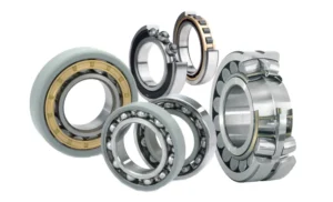
- If your equipment handles heavy loads or impacts (e.g., rolling mills, heavy machinery):
Your first choice should be a Roller Bearing.- The reason is simple: Rollers make “line contact” with the raceway, like the wide tires of a truck. This larger contact area gives them a naturally higher load-carrying capacity.
- If your equipment runs at high speeds with light to medium loads (e.g., electric motors, precision instruments):
A Ball Bearing is the more suitable option.- The reason is simple: Balls make “point contact” with the raceway, like the narrow tires of a racing car. This results in lower friction and allows for higher speeds.
With this basic choice made, we can then look at the direction of the load to select a specific type:
- For mainly Radial Loads (force perpendicular to the shaft):
- Ball Bearing → Deep Groove Ball Bearing (most versatile and cost-effective).
- Roller Bearing → Cylindrical Roller Bearing (much higher load capacity than a ball bearing).
- For both Radial and Axial Loads combined:
- Ball Bearing → Angular Contact Ball Bearing (good for high speeds and precision).
- Roller Bearing → Tapered Roller Bearing (high load capacity and rigidity).
- If there is potential for misalignment or shaft deflection:
- Choose a Self-Aligning Bearing (available in both ball and roller types), which can compensate for alignment errors.
By following these two simple steps—first considering the load magnitude, then the load direction—you can quickly narrow down the vast range of options to a few suitable candidates. This provides a solid foundation for the next steps in the selection process.
Step 2: Bearing Arrangement – Defining the Shaft’s Position
Expanded Explanation:
A single bearing cannot adequately support a shaft. We typically need at least two bearings working together in an “arrangement.” The most classic design is the fixed-floating arrangement.
- Fixed End: Uses a bearing that can handle both radial and axial loads (e.g., a deep groove ball bearing or a pair of angular contact ball bearings) to locate the shaft axially in both directions.
- Floating End: Uses a bearing that only supports radial loads (e.g., a cylindrical roller bearing). It allows the shaft to move slightly in the axial direction to accommodate thermal expansion, preventing internal stresses that could cause the bearing to seize.
This arrangement ensures precise shaft location while solving the problem of thermal expansion, making it the top choice for most designs.
Step 3: Size and Life – Quantifying Performance
Expanded Explanation:
You have now selected your bearing type (for example, a “tapered roller bearing”). You open the product catalog and find dozens of different sizes for that type. So, which size should you choose? The one with a 52 mm outer diameter, or the 80 mm one?
Guessing the size is not an option for engineers. We need a scientific method to answer the question: “How long will this specific bearing size actually last in my machine?” This is the purpose of life calculation.
To understand it, you only need to know two key values:
- The Bearing’s “Strength Score” – Basic Dynamic Load Rating (C)
- Think of this as a person’s “maximum strength.” This value is listed in the specifications for every bearing. Larger bearings have a higher C rating, meaning they are “stronger.”
- The Machine’s “Workload” – Equivalent Dynamic Load (P)
- This is the combined load that you calculate based on your machine’s actual operating conditions (speed, radial force, axial force). It represents the “weight” the bearing actually has to lift.
The core of life calculation is comparing the “Strength Score (C)” to the “Workload (P).”
- If C is much greater than P: It’s like asking a professional weightlifter to carry a bag of groceries. They can do it for a very long time without getting tired. This means the bearing will have a very long life.
- If C is close to P: It’s like asking a person to lift the heaviest weight they possibly can. They will get exhausted very quickly. This means the bearing life will be short.
Using a standard formula, this comparison between C and P gives us a result called the L10 Rating Life. This represents the lifespan that at least 90% of a group of identical bearings will achieve or exceed (usually measured in millions of revolutions).
Step 4: Precision & Fits – From “Able to Turn” to “Turning Precisely”
Expanded Explanation:
For applications like machine tool spindles, performance is about more than just load and life.
Precision class (e.g., P5, P4) defines the bearing’s own dimensional and rotational accuracy.
Meanwhile, fits (the tightness between the inner ring/shaft and outer ring/housing) and clearance (the internal gap between rolling elements and raceways) determine the bearing’s final state after installation.
It’s a balancing act: a tight fit reduces internal clearance, which can cause excessive preload and heat. A loose fit fails to provide adequate support and leads to vibration. Therefore, you must carefully select a combination of these three based on speed, load, and precision requirements.
Step 5: Preload & Rigidity – Increasing System “Stiffness”
Expanded Explanation:
In applications demanding extremely high rotational accuracy and system rigidity, even the slightest clearance is detrimental. Preload is the process of applying an external force (via a spring or nut) to eliminate the bearing’s internal clearance, putting it into a slightly compressed state.
The benefits are significant:
- Increased Rigidity: Eliminates gaps, so the shaft assembly deforms less under load.
- Improved Rotational Accuracy: Reduces shaft wobble and vibration.
- Reduced Noise: Prevents rolling elements from sliding and rattling in unloaded zones.
Angular contact ball bearings and tapered roller bearings are the most common types used for preloading.
Step 6: Lubrication – The “Lifeblood” for Continuous Operation
Expanded Explanation:
Lubrication is the lifeline for reliable bearing operation. The first decision is grease vs. oil.
- Grease Lubrication: Simple design, good sealing properties, and long maintenance intervals. Suitable for most industrial applications with moderate speeds and temperatures. It’s the convenient “fit and forget” solution.
- Oil Lubrication: Excellent flow, allowing it to effectively dissipate heat and flush away contaminants. Essential for high-temperature, high-speed, or demanding environments where precise lubrication is needed. Methods include oil baths, oil mist, and jet lubrication.
Choosing the wrong lubricant or lubrication method is one of the most common causes of premature bearing failure.
Step 7: Surrounding Components – A Good Horse Needs a Good Saddle
Expanded Explanation:
A bearing’s performance heavily relies on a well-designed “ecosystem.” Think of a high-performance tire: it needs a strong wheel and a finely-tuned suspension to deliver its full potential.
- Shaft and Housing: Must be sufficiently rigid with manufacturing tolerances that match the bearing’s precision class. The fillet radii on shaft shoulders and in housing bores must be smaller than the bearing’s chamfer to ensure proper seating.
- Seals: In contaminated environments (dust, water), seals are the bearing’s first line of defense. Choosing the right contact or non-contact seal can extend bearing life several times over.
If you neglect the design of these surrounding parts, even the best bearing will underperform.
Step 8: Mounting & Dismounting – Considering the Full Lifecycle
Expanded Explanation:
A great designer always considers “serviceability.” You should anticipate future installation and removal scenarios during the selection phase.
- Mounting: Is there enough space for proper tools (like induction heaters or hydraulic nuts)? Improper mounting (e.g., using a hammer) is a leading cause of early bearing damage.
- Dismounting: Have you designed features to make removal easier, such as withdrawal sleeves or threaded holes in the housing? Considering this will save the end-user significant maintenance time and costs.
Thinking in terms of the full lifecycle makes your design more valuable to your customers.
Conclusion & Selection Checklist
By following these 8 steps, you will establish a comprehensive and rigorous selection logic that effectively mitigates risks and maximizes equipment performance. This is not just about choosing a part; it’s about designing a reliable system.
Not finding what you need?
If you have enquiries about our product or solutionservice, please contact us via email.