


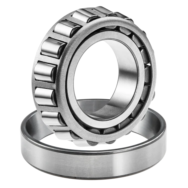


When to Replace a Bearing: Early Warning Signs and Maintenance Tips
This guide outlines the critical warning signs of bearing failure, such as noise, vibration, and heat. It explains the root causes of damage and provides actionable maintenance tips to help you determine exactly when to replace a bearing to ensure operational efficiency.

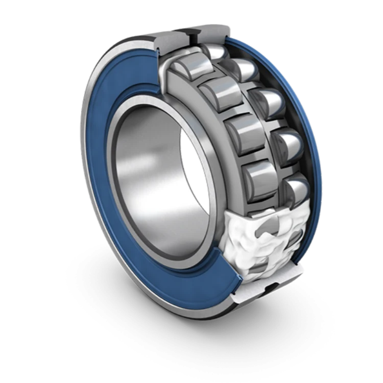
Why Proper Bearing Lubrication Matters: Types, Methods, and Maintenance Tips
This article explores the critical role of bearing lubrication in reducing friction and preventing failure. It covers the differences between grease and oil, proper application methods, common mistakes to avoid, and maintenance strategies to ensure industrial machinery operates efficiently.
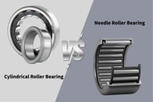
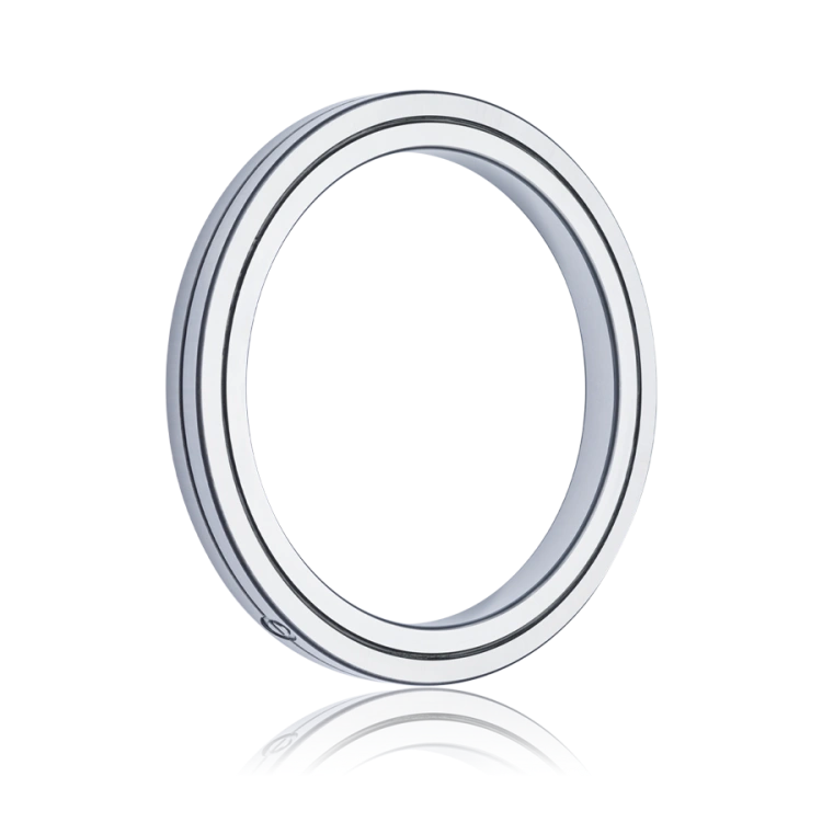
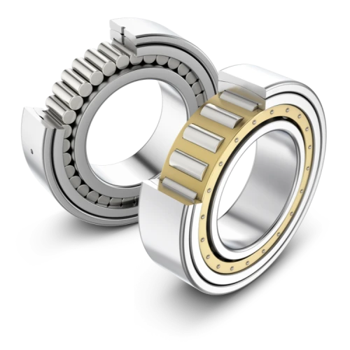
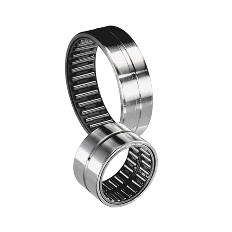
Cylindrical Roller Bearings vs Needle Roller Bearings: A Detailed Comparison
This technical guide provides a side-by-side comparison of cylindrical vs needle roller bearings, analyzing their structural differences, load capacities, and speed limitations. It offers engineers and buyers practical advice on selecting the right bearing type to optimize machinery performance and space efficiency.
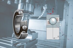
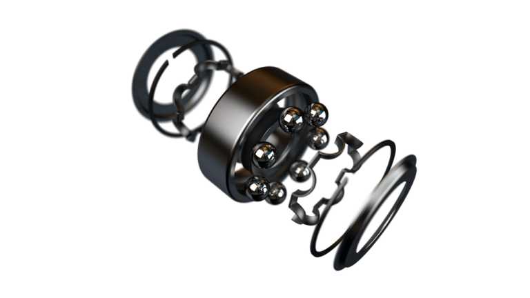
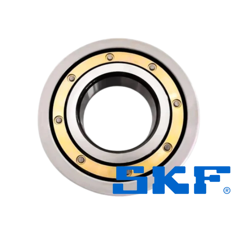
Angular Contact Ball Bearings: Features, Benefits, and Best Applications
This article explores the design, functionality, and benefits of angular contact ball bearings, highlighting their ability to handle combined loads in high-speed industrial applications like robotics and automotive systems.