Knowledge Center
Bearing Preload: An Angel or a Devil?
In our previous articles, we discussed “clearance”—the essential “breathing room” inside a bearing. Today, we explore the exact opposite concept: Preload. Preload is the process of intentionally removing clearance to apply an initial internal load to a bearing. Think of it like tuning a guitar string. Only with the right tension can it produce a beautiful note.
However, if the tension is too high, the string will snap. Bearing preload is the same. It’s a double-edged sword: an “angel” that enhances performance when used correctly, and a “devil” that causes disaster when done wrong.
Section Navigation
#1 Precision, Clearance and Preload
#2 Bearing Failure Analysis Atlas
#3 Cost & Efficiency Optimization & Reliability Upgrade
What Is Preload and Why Do We Need It?
Simply put, preload is a specific, constant axial force applied to a bearing to create negative clearance before it is subjected to any external working loads.
Why do we do this? The “angelic” side of preload offers four key benefits:
- Increased Rigidity (Stiffness): A preloaded bearing has constant, firm contact between its rolling elements and raceways. When an external load is applied, it deforms very little. This is critical for applications requiring extreme precision, like machine tool spindles.
- Improved Running Accuracy: Preload eliminates internal wobble, significantly reducing the shaft’s radial and axial runout. This makes its rotational path much closer to a perfect circle.
- Reduced Noise and Vibration: Under light loads or at high speeds, rolling elements without preload can “skid” or “chatter,” creating noise. Preload ensures they always roll smoothly.
- Extended Life (in some cases): In certain applications, proper preload can distribute the load more evenly across more rolling elements, thereby extending the bearing’s fatigue life.
The Main Characters – Angular Contact Ball Bearings
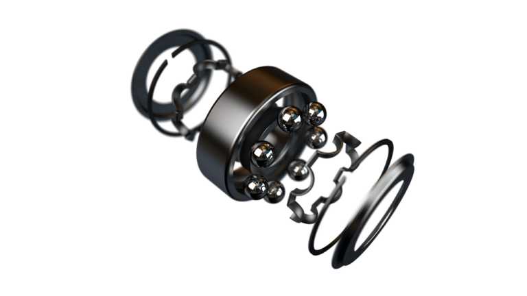
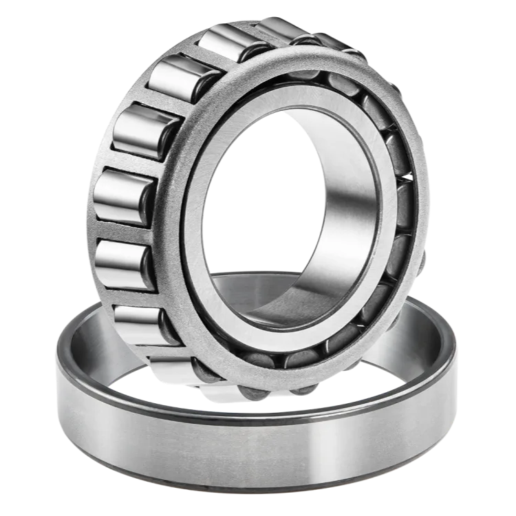
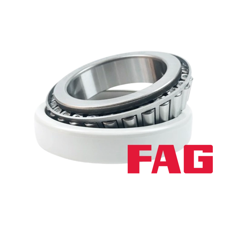
Not all bearings are suitable for preload. The primary candidates are bearings that can handle bi-directional axial loads, most typically pairs of angular contact ball bearings (ACBBs) and tapered roller bearings.
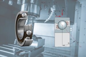
The unique geometry of ACBBs (their contact angle) makes them perfectly suited for precise preload control through axial adjustment. They are usually mounted in pairs in three classic configurations:
Arrangement | Code | Diagram Concept | Features & Preload Method |
Back-to-Back | DB | Outer ring wide faces are adjacent. Load lines diverge outward. | Highest rigidity and best resistance to tilting moments. Preload is applied by tightening a locknut to pull the inner rings together. |
Face-to-Face | DF | Outer ring narrow faces are adjacent. Load lines converge inward. | Less rigid than DB, but more tolerant of shaft misalignment. Preload is applied by clamping the outer rings. |
Tandem | DT | Both bearings face the same direction. Load lines are parallel. | Does not provide two-way location; it increases axial load capacity. It cannot be preloaded by itself and must be opposed by another bearing (or pair) to preload the system. |
How to Apply Preload – Methods and Precise Control of the Amount
A Closer Look at the Two Preload Methods:
Constant Position Preload
- Core Idea: To achieve a fixed axial displacement (δ₀) by precisely controlling the dimensions of the components. This displacement is the source of the preload.
- Common Techniques:
- Using Matched Spacers: Manufacturing a pair of spacers where the inner and outer ring spacers have either the same height or a specific height difference. During assembly, you simply tighten the locknut to the recommended torque, and the spacer dimensions precisely set the preload. This is the most reliable and common method.
- Adjustment with a Locknut: Without spacers, preload is adjusted by controlling the tightening angle or torque of a precision locknut. This method requires a dial indicator to monitor the axial displacement or a torque wrench to control the force, demanding high assembly skill.
- Best for: Applications needing maximum rigidity with minimal temperature variation, such as machine tool spindles.
Constant Pressure Preload
- Core Idea: To apply a constant preload force (F₀) using elastic components like springs.
- Common Techniques:
- Using Springs: Placing a spring or a set of springs (e.g., disc springs or wave springs) between one of the bearing rings (usually the outer ring) and the housing. The amount the spring is compressed determines the preload force.
- Best for: High-speed applications with significant temperature changes or where vibration damping is needed, such as in high-speed motors or the support end of ball screws.
Calculating and Measuring Preload – From Theory to Practice
Applying preload is not just about choosing the right method (position vs. pressure); it’s about setting the right preload amount.
How Preload is Calculated (Example for ACBBs)
Calculating preload is a complex but logical process. The goal is to optimize the bearing’s contact angle, rigidity, and life under operating conditions.
Basic Formula: F₀ = Kδ * δ₀
- F₀: The initial preload force (N)
- Kδ: The bearing’s axial stiffness (N/mm), a key parameter found in the manufacturer’s technical catalog or software. It represents the bearing’s resistance to axial deformation.
- δ₀: The initial axial displacement (mm), which is the gap we close by using spacers or adjustment.
Example: A Simplified Preload Calculation for a 7008C Bearing
Let’s use a common machine tool spindle bearing, the 7008C (with a 15° contact angle), to walk through a simulated calculation.
Step 1: Look Up the Technical Data
From the bearing manufacturer’s catalog, we find the key parameter for a 7008C bearing:
- Axial Stiffness (Kδ): Let’s assume the value is 390 N/µm (or 390,000 N/mm). This means it takes 390 Newtons of force to axially displace the bearing rings by just 1 micron (0.001 mm).
Step 2: Determine the Preload Class
Based on the machine’s requirements, we choose a Light Preload. The manufacturer’s recommended light preload force (F₀) for a 7008C bearing is:
- Recommended Preload Force (F₀): 260 N (Newtons)
Step 3: Calculate the Required Axial Displacement
Now, we can use our formula F₀ = Kδ * δ₀ to calculate how much axial displacement we need to apply to achieve a 260N preload force.
- Calculation:
- δ₀ = F₀ / Kδ
- δ₀ = 260 N / 390 N/µm
- δ₀ ≈ 0.67 µm (microns)
Conclusion:
This means that to apply a standard light preload to a 7008C bearing, we need to use precision spacers or a locknut to create an axial displacement of about 0.67 microns (or 0.00067 millimeters) between the inner and outer rings. This is an incredibly small dimension! It explains why preload assembly requires high-precision parts and specialized tools, as even a tiny error can cause a massive change in the final preload force.
In reality, the calculation is much more involved. Engineers typically consider:
- Required Stiffness: Determine the target axial and radial stiffness for the system based on the machine’s performance requirements.
- Initial Preload Selection: Choose an initial preload force F₀ based on experience or the manufacturer’s recommendations (often categorized as Light, Medium, or Heavy preload).
- Thermal Effects: Calculate how much the preload will increase (ΔFₜ) due to heat generated at the expected operating speed and load. This is the most critical step, because the Operating Preload F_op = F₀ + ΔFₜ.
- Verify Operating Preload: Check if the final operating preload F_op is excessive, which could lead to extreme contact stress or a shortened service life. If it’s too high, they must go back and reduce the initial preload F₀.
- Calculate Displacement/Spacer Size: Once the optimal initial preload force F₀ is determined, they use the stiffness formula to calculate the required axial displacement δ₀, and then design the spacers to these dimensions.
Important Note: For end-users, you are usually not expected to perform these complex calculations yourself. The more practical approach is to follow the equipment manufacturer’s service manual or use pre-matched bearing sets that come with a specified preload class (e.g., L-Light, M-Medium, H-Heavy).
Measuring and Verifying Preload
After the theoretical calculation, how can you verify that the preload is correct during assembly?
- Measuring Starting Torque: This is the most common and direct on-site verification method.
- Principle: A bearing’s frictional torque is directly proportional to its internal preload. The higher the preload, the more torque is needed to start its rotation.
- Method: Immediately after the bearing is assembled, and before grease is applied (or with only the factory rust-preventive oil), use a precision torque wrench or torque meter. Slowly turn the shaft (or bearing ring) and record the minimum torque required to begin and maintain smooth rotation.
- Evaluation: Compare the measured starting torque to the standard range provided by the bearing manufacturer or in the equipment manual.
- Torque too high: Indicates excessive preload.
- Torque too low: Indicates insufficient preload or no preload at all.
- Torque within range: Indicates the preload is likely correct.
- Monitoring Operating Temperature:
- Method: During the initial run-in of the equipment, use an infrared thermometer or a contact thermometer to constantly monitor the temperature of the bearing housing.
- Evaluation: If the temperature rises sharply in a short period and goes well beyond the normal range (e.g., exceeds 70-80°C and is still climbing), it is a strong signal of excessive preload. The machine should be stopped and inspected immediately.
The Devil’s Side: Dangers of Excessive Preload
Applying too much preload is one of the most fatal errors in bearing application. It triggers a chain reaction of failures:
- Rapid Temperature Rise: The excessive internal pressure causes a massive increase in friction, generating far more heat than the bearing can dissipate.
- Lubricant Failure: High temperatures cause the grease or oil to break down and lose its lubricating properties, leading to metal-to-metal contact.
- Drastically Reduced Life: The high contact stress accelerates material fatigue, making the bearing’s actual life much shorter than its calculated life.
- Catastrophic Failure: In extreme cases, the bearing will overheat, seize, and fail completely, leading to costly equipment downtime and damage.
Taming the Devil with Precision
Preload is a sophisticated engineering technique. It’s not a “yes or no” question, but a “how much” calculation. It gives bearings extraordinary rigidity and accuracy, but it also comes with great risk. Only through precise calculation, selecting the right method (position or pressure), and using proper installation techniques can we harness this powerful force. By doing so, we can turn the “devil” into an “angel” that protects and enhances our high-precision equipment.
Not finding what you need?
If you have enquiries about our product or solutionservice, please contact us via email.